How to measure the compression for Mechanical Seal of Double Support Centrifugal Pump?
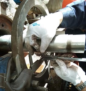
Step 1: Measure the distance between bearing box and suspension contact surface and bearing box and bearing skin end face.
a. Use a depth rule from the contact plane between the bearing box and the gland to the contact plane between the bearing box and the end face of the bearing skin (e.g.; Distance is 109.4mm minus vernier caliper thickness 4mm=105.4mm).
b. Use vernier calipers to measure the contact plane between bearing and gland to the contact plane between bearing box and suspension (e.g.; Distance is 115mm minus depth gauge thickness 5mm=110mm).The number of a is 105.4mm and the number of b is 110mm= the distance between bearing box and suspension contact surface and bearing box and bearing skin end surface is 4.6mm.
Step 2: Install the shaft sleeve and moving ring on the shaft.
The purpose of installing the shaft sleeve first is; To prevent the thrust of the shaft sleeve after adjusting the position of the shaft from changing the position of the shaft, which is useless and has to be adjusted repeatedly.
From the contact end face between shaft and bearing inner ring to the contact plane between suspension and bearing box (e.g. Add the measured data to the depth gauge thickness of 4mm, and adjust the end face of the shaft shoulder to be 4.6mm higher than the suspension plane through the copper rod (hammer) slight axial tapping method. At this time, the rotor is in the position of half string capacity after normal installation (also known as the normal operation position of the rotor).
Note: When measuring, pay attention to whether there is a half series adjustment pad between the end face of the bearing inner ring and the end face of the shaft shoulder, and it is necessary to install the measurement or add the thickness dimension.
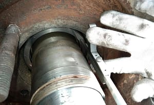
Step 3: From the sealing cavity and the sealing end face of the machine seal gland to the sealing surface of the moving ring.

Step 4: Measure from the end face of the machine seal cover and sealing cavity to the sealing surface of the static ring (example number is 29.7mm)29.7mm minus the third step 25.7mm= the final compression of 4mm.
Note: When the drive end seal measures the compression amount, it is also necessary to place the rotor in the half-string position for measurement. If the non-drive positioning bearing is not removed, the position of the rotor can be ignored and the third and fourth steps can be directly carried out. Packing mechanical seal does not need to measure the compression amount, after all the work is done to fix the shaft sleeve radial top wire, loosen the compression adjustment sheet.
Learn more our project quality managemet, QAQC and third party inspection (TPI), NDT practices thru below link.
https://www.jsc-safe.com/steel-structures-modules-machining/

