Five Steps to Calibrate Magnetic Testing (MT) Equipment
Five Steps to Calibrate Magnetic Testing (MT) Equipment – There are many kinds of magnetic particle testing equipment, from small portable magnetic detector to wet horizontal magnetic detector to high current fixed magnetized power supply for large structures.
If you follow ASTM E1444, ASTM E3024, ISO 9934, or NADCAP AC7114/2, you must calibrate your equipment every six months. No matter what type of magnetic particle testing equipment is used, five-step method can be used for equipment calibration.
Step 1: verify the standard instrument to be used
1.This work requires standard reference instruments: shunts, ammeters, and excitation timers. Different instruments have different control configurations. Refer to the specification of the standard reference instrument for detailed operating procedures.
2.Check the calibration dates of these standard reference instruments-have they been calibrated in the past 6 months?
3.How much data do you need to test and record? The total amount of data depends on the device configuration. Test data is collected for each current type (AC, HWDC, FWDC) and each output channel (conductive plate, coil, auxiliary output device) owned by the equipment.
Step 2: Ammeter accuracy
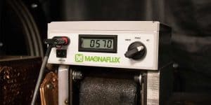
1.Connect the shunt to the output circuit in series and connect the leads to a standard ammeter.
2.Presets the output magnetization current to the middle of the device’s available range.
3.Activate excitation and record device ammeter and standard ammeter readings.
4.Calculate the difference between the two readings and compare it with the permissible error (+/-10% or 50 A, whichever is greater) .
5.The above detection is repeated at least 3 points within the usable output range of the device.
6.Repeat this step for each current type (AC, HWDC, FWDC) on the same output channel.
7.Repeat the process for each output channel of the device (conductive plate, coil, auxiliary output device).
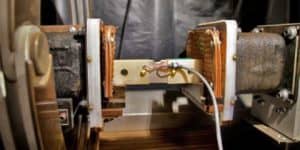
Ectromagnetic contact of conductive plate, clamp the shunt between head seat and tailstock:
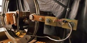
Coil electromagnetization, the shunt is connected in series to the coil on the machine:
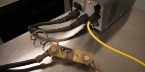
Cable winding coils and portable magnetic probes, the shunt is connected in series to the cable:
Step 3: verify the standard equipment to be used
1.Presets the output magnetization current to the minimum ampere value used.
2.Activate excitation and record the reading on the equipment ammeter.
3.To determine the tolerance and the acceptable range of the display value of each output current at repeated starting excitation (+/-10% or 50 A, whichever is larger).
4.The excitation is repeated until at least six ammeter readings are taken and each reading is compared with a defined acceptable range.
5.Repeat the above procedure for each current type (AC, HWDC, FWDC) on the same output channel.
6.Repeat the process for each output channel of the device (conductive plate, coil, auxiliary output device).
Step 4: electromagnetize time
1.Place the timer on the device according to the specifications for the verification of the magnetization time used.
2.Presets the output magnetization current to the middle of the device’s available range.
3.Start excitation and record the reading of the magnetization time check timer.
4.The reading should be within +/-0.1 seconds of the magnetization time set on the magnetometer.
5.If the device has a separate controller for each output channel, repeat the process separately.
Step 5: only suitable for three-phase full-wave DC output (3-phase FWDC) magnetic detector fast power cut test
1.Put the quick power-off tester into the equipment coil and operate according to the specific instructions of the instrument. Fast power-off test is available only for 3-phase full-wave DC (3-phase FWDC-RRB- magnetometers, coil or cable coils only.
2.Set the magnetizing current to provide a magnetic potential of 15,000 ampere turns.
Set the magnetizing current to 3000a for the coil on the 5-turn horizontal machine;
For 3-turn cable winding coils, set the magnetizing current to 5000a.
3.Activate the excitation and observe the results on the quick power-off tester used. There are two types:
Go/no-Go meter (similar to QB1 Type): observe the flashing of indicator lights during electromagnetization. The indicator light may flash at the beginning or end of the pass electromagnetization, or in both cases. Any sparkle is the result of expectation. Repeat 20 pass electromagnetic, should have at least 80% of the light flashing occurred. Go/no-Go gauges are available only for coils with a diameter of 25 inches or less per 63.5 cm.
Digital Ammeter (similar to QB2) : compare the reading with the minimum voltage induced by a quick power cut in the following control meter. The minimum acceptable voltage (V) depends on the diameter of the coil.
Calibrating the magnetic particle testing equipment according to these five steps. Be sure to keep records of calibration data to demonstrate compliance with ASTM, ISO and NADCAP standards.
Learn more our project quality managemet, QAQC and third party inspection (TPI), NDT practices thru below link.-