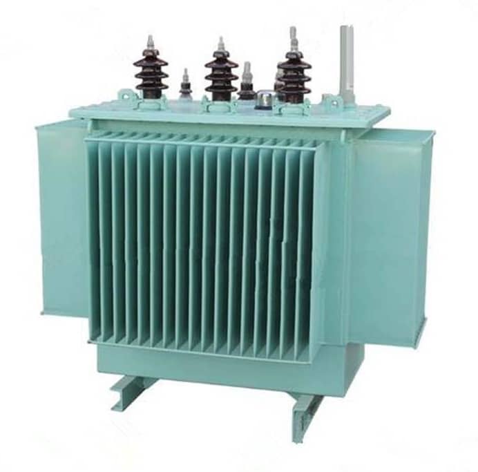
Test Method of Transformer
Test Method of Transformer
1.Check whether there are obvious anomalies by observing the appearance of the transformer.
Such as whether the coil lead is broken, de-soldering. Whether the insulation material has burnt marks. Whether the core fastening screw is loose.Whether the silicon steel sheet is corroded. whether the winding coil is exposed, etc.
2.Insulation performance test.
Use the multimeter R×10k stop to measure the resistance value. Between the core and the primary, the primary and the secondary, the core and the secondary, the electrostatic shielding layer and the secondary and secondary windings, and the multimeter pointer should mean that the infinite position is not moving. Otherwise, it indicates that the insulation performance of the transformer is poor.
3.Coil on and off detection.
The multimeter is placed in R×1 gear, and in the test, if the resistance value of a winding is infinite, it indicates that this winding has an open fault.

4.No-load current detection.
(a) Direct measurement method. With all secondary windings open, set the multimeter in AC current gear (500mA) and string it into the primary windings. When the plug of the primary winding is inserted into the 220V AC mains, the no-load current value is indicated by the multimeter. This value should not be greater than 10% to 20% of the transformer full load current. Generally, the normal no-load current of the power transformer for electronic equipment should be about 100mA. If it exceeds too much, it indicates that the transformer has a short-circuit fault.
(b) Indirect measurement method. A 10/5W resistor is connected in series in the primary winding of the transformer, and the secondary is still all empty. Set the multimeter to AC gear. After powering up, use two pens to measure the voltage drop U at both ends of the resistance R, and then use Ohm’s law to calculate the no-load current I null, that is, I null =U/R.
5.No-load voltage detection.
The primary power transformer is connected to 220V mains, and the AC voltage of the multimeter is connected to measure the no-load voltage of each winding (U21, U22, U23, U24) in turn. The allowable error range is generally: the high voltage winding is ≤± 10%, the low voltage winding is ≤± 5%, and the voltage difference between the two groups of symmetric windings with center tap should be ≤±2
6.Detect and distinguish the same end of each winding.
When using a power transformer, sometimes two or more secondary windings can be used in series in order to obtain the required secondary voltage. When the power transformer is used in series, the same end of each winding participating in series must be correctly connected and cannot be mistaken. Otherwise, the transformer will not work properly.
Learn more our project quality managemet, QAQC and third party inspection (TPI), NDT practices thru below link.
